Five‑Axis Machining Centers: Improving Yield and Cycle Time in Automotive Intelligent Manufacturing
2025-12-31
Industry Research
As automotive production shifts toward intelligent manufacturing and lightweight designs, conventional three‑axis machining increasingly struggles to meet the precision and throughput requirements of complex components. This article explains how five‑axis high‑speed CNC machining centers — through multi‑axis synchronized cutting, reduced workpiece setups and optimized toolpaths — can raise first‑pass yield by an estimated 10–30% and shorten cycle time by 20–50% in typical engine block and transmission housing workflows. Case analyses and process improvement points illustrate tangible benefits (setup reductions up to ~60%, lower manual intervention, and more consistent geometric accuracy) and outline practical steps for manufacturers to integrate five‑axis strategies into smart production lines.

Automotive Smart Manufacturing Upgrade: How Five‑Axis Machining Centers Improve Yield and Production Rhythm
As automotive programs push for lighter, more complex components and tighter tolerances, conventional three‑axis machining increasingly limits quality and throughput. This paper examines how five‑axis high‑speed CNC centers address core production pain points—reducing setups, improving first‑pass yield and shortening cycle times—through multi‑axis kinematics, optimized toolpaths and integrated process control.
The manufacturing gap: why three‑axis often falls short
Automotive powertrain and chassis components now demand multi‑surface contouring, undercuts and thin‑wall features that stress tooling and fixturing. Key limitations of three‑axis machining include:
- Multiple workpiece re‑setups (commonly 3–5 per part), increasing cumulative fixture error and operator time.
- Limited tool approach angles, forcing long, slender cutters that reduce stability and tool life.
- Longer cycle times due to slower contouring strategies and frequent manual inspections.
- Higher scrap and rework rates driven by misalignments and insufficient machining access.
How five‑axis centers close the gap: core technical advantages
Five‑axis simultaneous machining offers several process advantages directly relevant to automotive requirements:
- Reduced setups: Multi‑face access in one clamping reduces positional error accumulation and logistics overhead—typical reduction is 60–80% in setups for complex castings.
- Improved cutting conditions: Optimal tool orientation shortens engagement, enables larger diameter tooling and increases feed per tooth—tool life often improves 20–40%.
- Higher geometric accuracy: Single‑setup machining cuts datum transfers between faces; tolerances of 0.01–0.03 mm are routinely achievable for critical features.
- Cycle time savings: Consolidated operations and aggressive toolpaths yield cycle reductions commonly in the 20–40% range for multi‑surface parts.
- Process automation and feedback: Integrated probing, adaptive control and pallet systems reduce human intervention and support closed‑loop quality control.
Quantified industry indicators (typical ranges)
Performance improvements observed in production lines after five‑axis adoption:
| Setup count (complex parts) |
Reduced by 60–80% |
| Cycle time |
Reduced by 20–40% |
| First‑pass yield / FPY |
Improved by 6–12 percentage points |
| Tool life |
Improved 20–40% |
Visualizing impact
Relative improvement vs. three‑axis baseline
Case study: engine block machining
A mid‑volume powertrain supplier transitioned a family of V‑6 engine blocks from multi‑op three‑axis cells to a five‑axis high‑speed center with pallet automation. Previously each block required four setups and offline inspection steps. After implementation:
- Setups dropped from 4 to 1 (single‑setup machining), eliminating 3 manual re‑fixtures per part.
- Cycle time decreased by 34% through optimized 5‑axis toolpaths and larger stable cutters.
- First‑pass yield improved from 88% to 96%; scrap and rework drivers related to datum transfer errors were nearly eliminated.
- Average tool life increased by ~28% due to better approach angles and reduced cutting vibration.
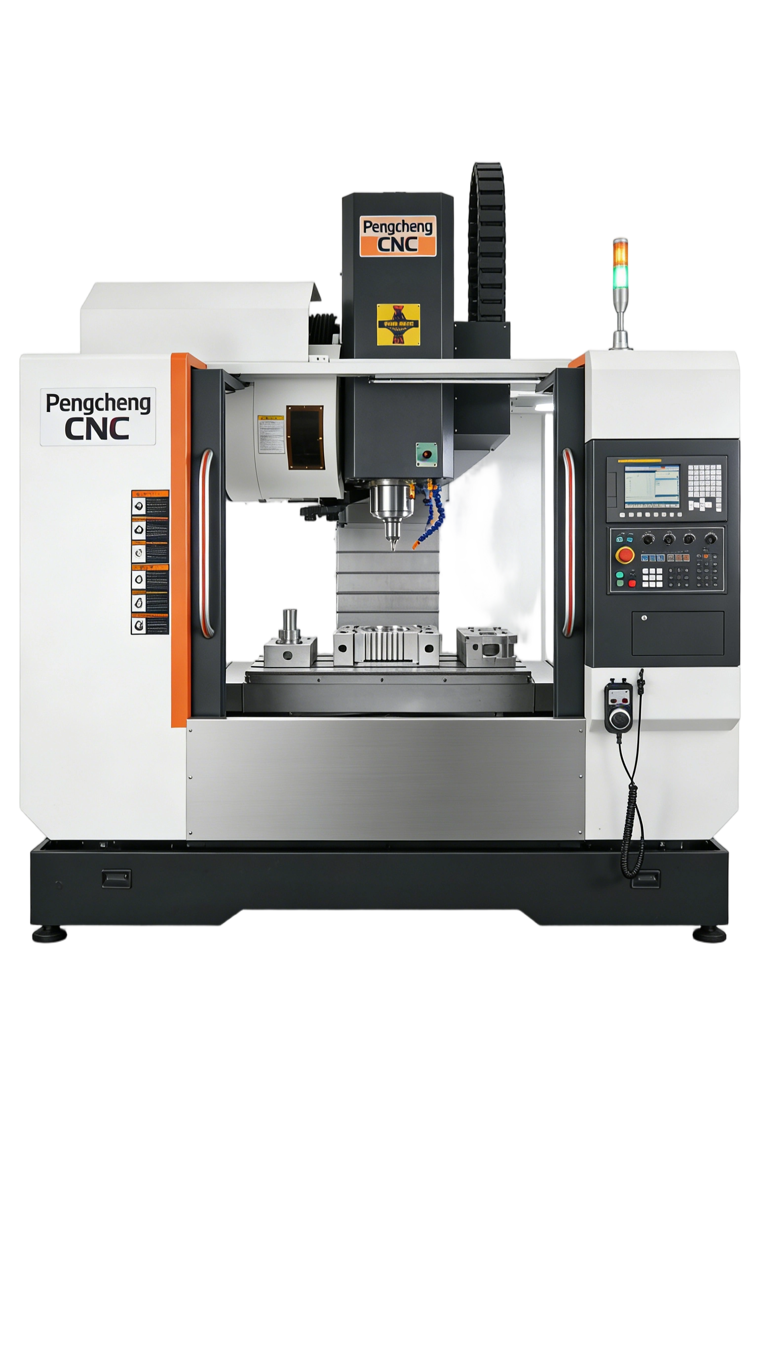
CNC machining center performing multi‑face finishing on an automotive engine block to reduce setups and improve precision" style="max-width:100%; height:auto; border-radius:6px; border:1px solid #DEE2E6;">
Case study: transmission housing & thin‑wall components
A supplier of transmission enclosures used five‑axis machining combined with dynamic balancing and adaptive feed control to stabilize thin‑wall features. Results included:
- Dimensional conformance improved into the 0.01–0.02 mm range for critical bores and sealing faces.
- Scrap rate for thin‑wall variants fell from about 6% to 1.5% after implementing five‑axis finishing and in‑cycle probing.
- Cycle times dropped 22% by eliminating secondary milling and deburring stations.
Process and implementation roadmap (practical steps)
A staged approach minimizes disruption and accelerates measurable benefits:
- Part selection (0–4 weeks): Identify 2–3 high‑complexity, high‑scrap parts for pilot.
- CAM and simulation (4–8 weeks): Develop 5‑axis toolpaths, collision checks and virtual verification.
- Fixturing & probing setup (2–6 weeks): Consolidate fixtures; integrate on‑machine probing routines for datum verification and adaptive offsets.
- Pilot production (1–3 months): Run limited volume, collect FPY, cycle time and tool life metrics; iterate CAM parameters.
- Scale and automation (3–12 months): Add pallet changers, robotic loading and OEE integration to capture full production benefits.
Key engineering levers for consistent results
To realize the quantified improvements, three technical levers are most effective:
- CAM strategy: Smooth, high‑feed toolpaths with rest‑machining, trochoidal roughing and advanced lead‑in/out reduce heat and vibration.
- Fixture consolidation: Design datum fixtures that enable single‑clamp machining; use vacuum or hybrid locators for castings.
- Process control: Combine on‑machine probing, adaptive spindle control and tool‑condition monitoring for closed‑loop adjustments.
Expected ROI timeline and KPIs
Payback typically depends on part throughput and labor cost structure; many suppliers report a 12–36 month payback when five‑axis is paired with automation and CAM optimization. Trackable KPIs during the ramp include FPY, cycle time per part, tool cost per part and operator touch time.

 413
|
413
|
 5-axis gantry machining center
Chain magazine configuration
Tool changeover time optimization
MES Integration
Smart manufacturing
5-axis gantry machining center
Chain magazine configuration
Tool changeover time optimization
MES Integration
Smart manufacturing


.png?x-oss-process=image/resize,h_500,m_lfit/format,webp)


